Today, we would like to introduce the CADmeister MOLD CREATOR Package.
~ What’s CADmeister MOLD CREATOR Package? ~
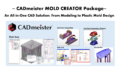
- An integrated CAD package specialized for mold design, combining modeling (BASE / ADVANCE) and mold design (MOLD CREATOR).
CADmeister MOLD CREATOR Package enables the following processes in a single environment:
- Modeling
- Mold Feasibility Analysis
- Parting Design
- avity and Core Design
- Insert Design
- Conceptual Mold Design
- Detailed Mold Design
- Drawing Creation
- Production Information Setup and Display
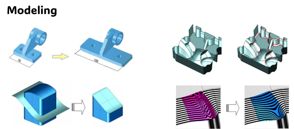
1. Modeling
For CADmeister modeling functions, please see our previous blog.
2. Mold Feasibility Analysis
During design reviews or prototyping, we sometimes find insufficient draft angles or undercuts, which require mold structure changes. Can these be checked at an early stage?
Yes. MOLD CREATOR has mold feasibility analysis functions.
It automatically checks the following items in the early design stage and displays problem areas with color highlighting:
- Thin wall areas
- Thick sections
- Draft angle Sharp edges
- Minimum corner radius
- Insufficient clearance
- Undercuts
- Projected area
- Parting line
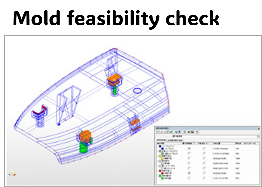
If problems can be identified at an early stage, it will reduce rework and help improve quality.
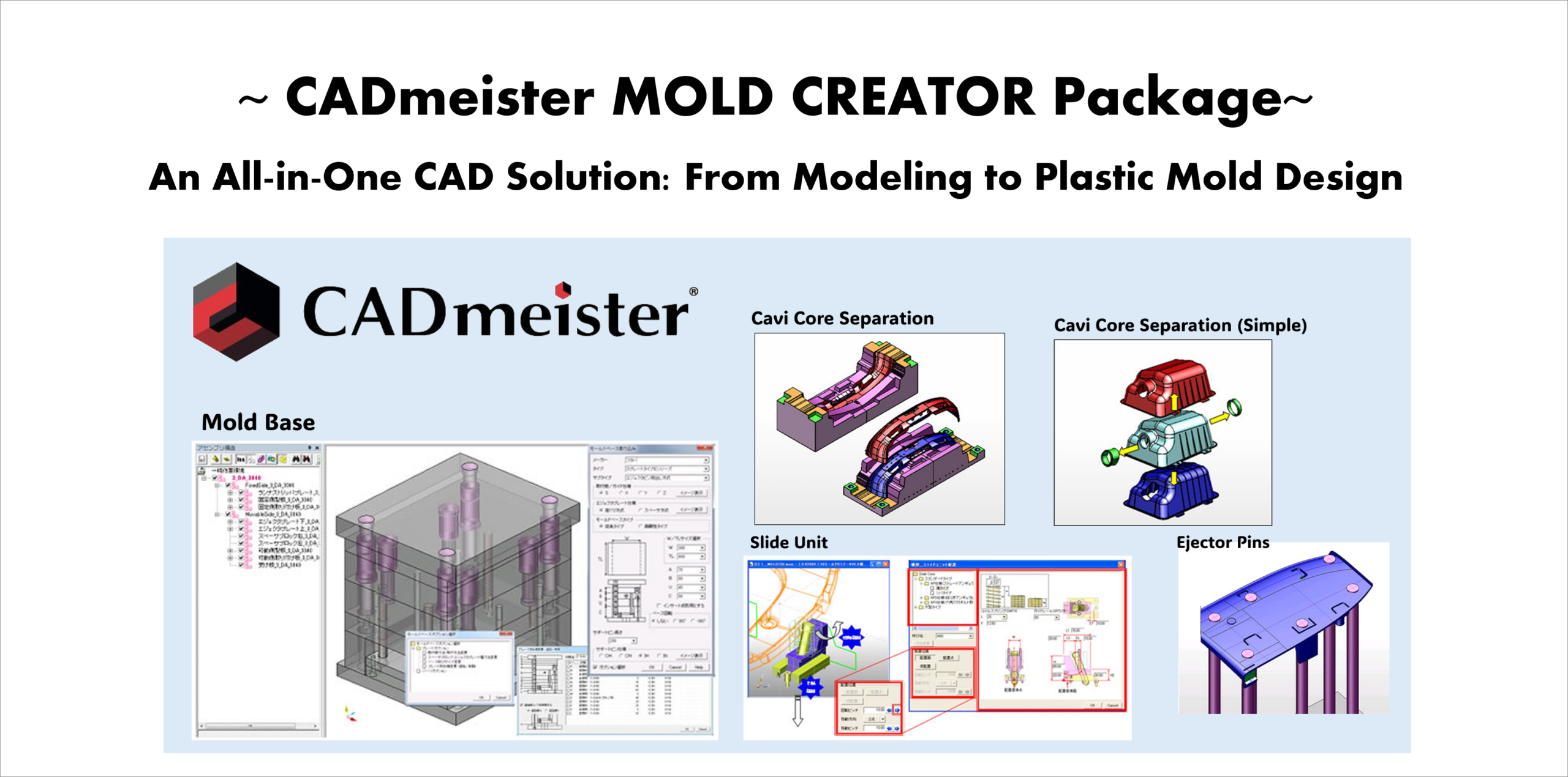
3. Parting Design
When the product shape is complex, it takes time to create parting lines and parting surfaces for Cavity and Core separation.
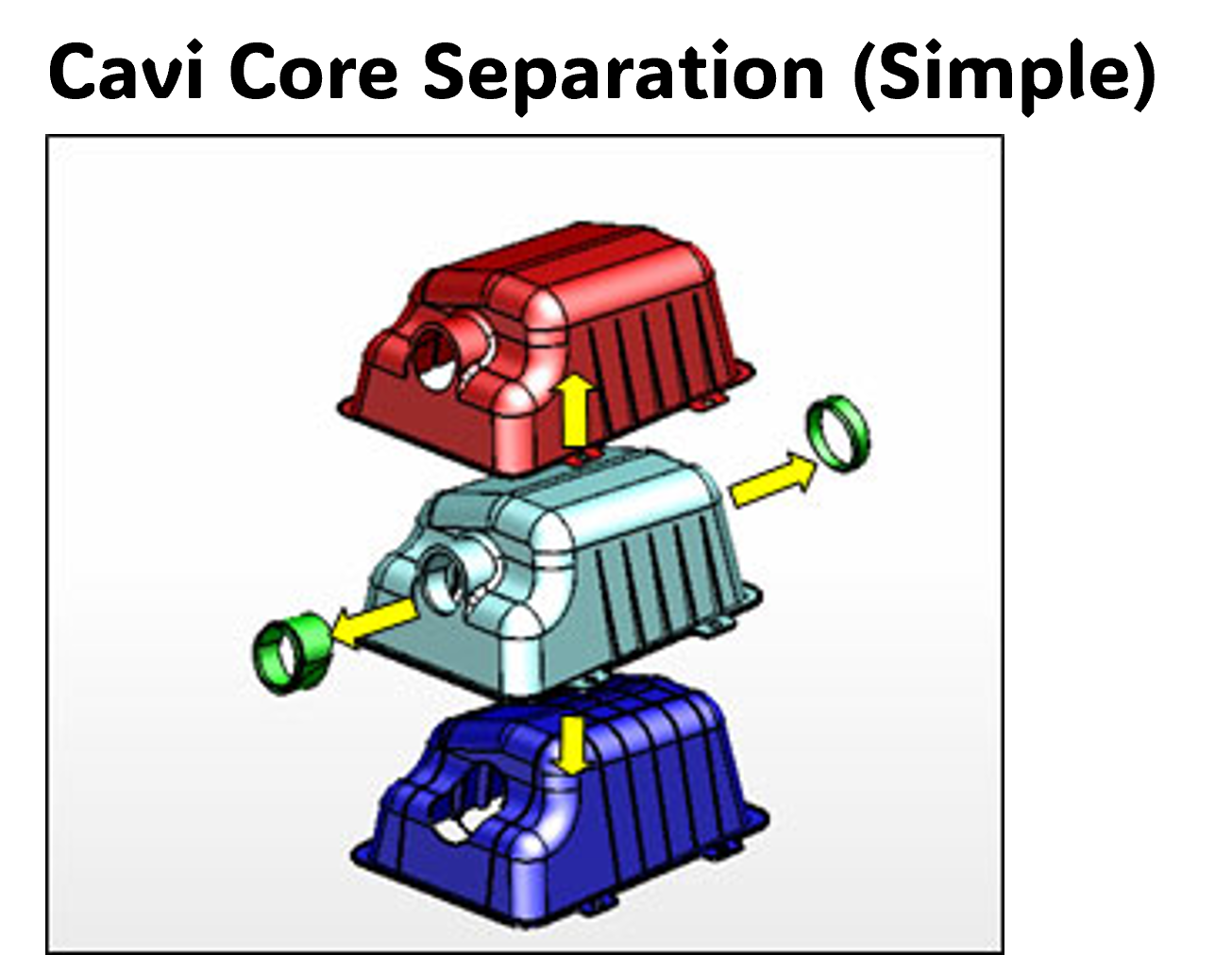
With the “Cavity/Core Separation (Simple)” function, you can visually check the draft direction and quickly detect undercuts.
In addition, the “Cavity/Core Separation” function uses PL lines and PL surfaces to efficiently create parting lines and separate the cavity and core. Even complex models can be split easily.
Does it support surface models as well?
Yes. It supports not only solid models but also large surface models for parting.
4. Cavity and Core Design
We create parting lines and PL surfaces manually, and hole processing takes especially a lot of time.
These tasks can be automated using the PL line creation, PL surface creation, and hole PL surface functions.
PL lines can be created from the product shape, and continuous PL surfaces can be generated automatically.
In addition, hole features are automatically recognized, and PL surfaces for holes can be created at once.
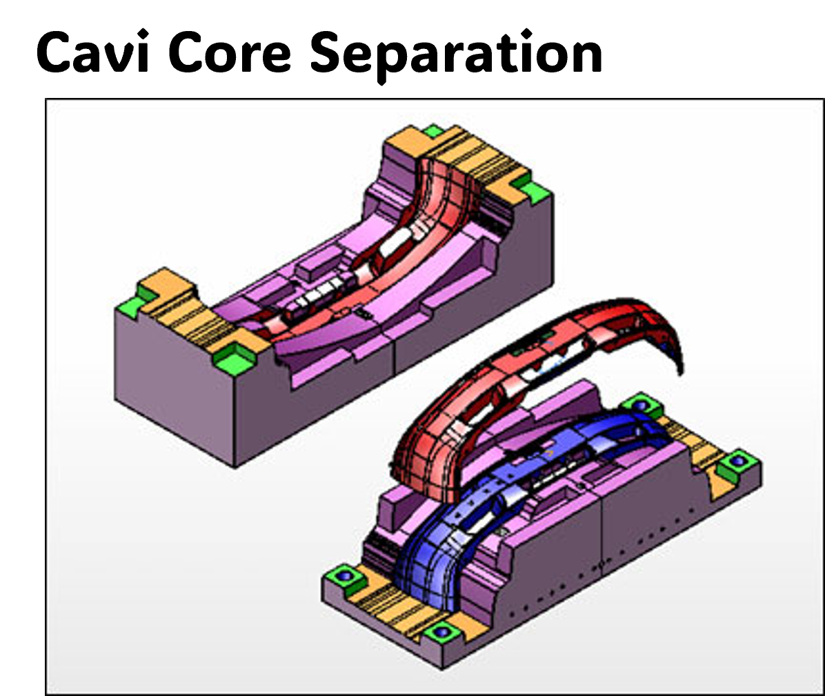
That will significantly reduce the effort needed for PL surface creation.
5. Insert Design
During insert design, it takes time to determine split positions and perform the splitting work.
You can split the inserts simply by entering the split line, through condition, and offset value. It also supports surface models.
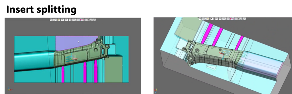
This helps significantly reduce insert design time.
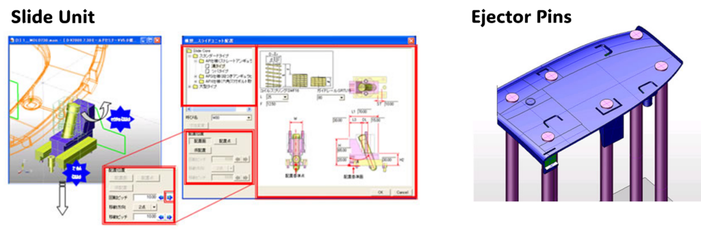
6. Conceptual Mold Design
When placing Ejector Pins and Slides, a lot of time is spent on position adjustments and interference checks.
The following conceptual design functions help improve efficiency:
- Slide Unit placement
- (Standard units can be selected and placed easily, making position adjustment and interference checking simple)
- (Standard units can be selected and placed easily, making position adjustment and interference checking simple)
- Automatic Ejector Pin placement
- (Standard units can be selected and placed easily, making position adjustment and interference checking simple)
- Inclined Core Unit placement
- (Units can be automatically placed by setting the angle)
- Cooling channel placement
- (Cooling circuits can be designed easily, including routing and connection layout)
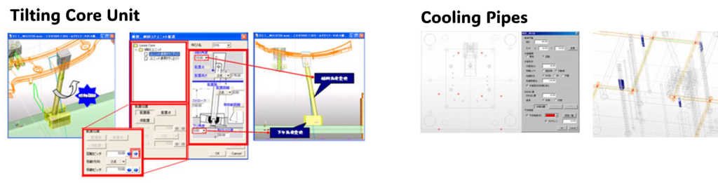
It’s useful because we can make layout adjustments while experimenting with different options.
7. Detailed Mold Design
Manually creating standard mold base layouts and plate structures each time requires a lot of time and effort.
You can import standard mold bases and manage each plate in an assembly structure, enabling parallel design and helping to shorten the design period.
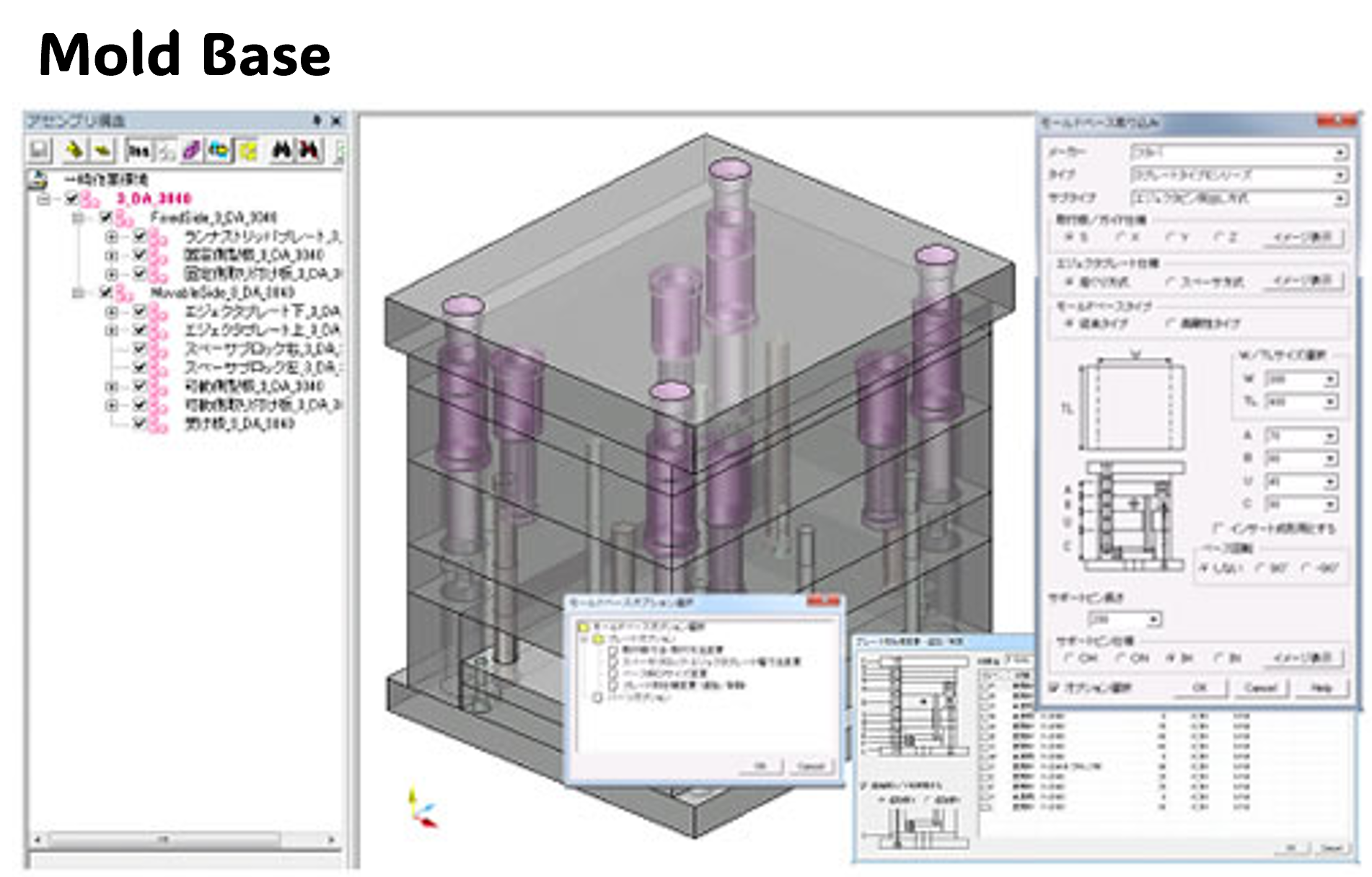
By managing each plate and component separately, multiple designers can work in parallel, which is highly beneficial.
8. Drawing Generation
We spend a lot of time creating drawings such as assembly drawings and part drawings, as well as adding dimensions.
You can automatically generate the following drawings from 3D data:
- Simplified drawings with dimension tables
- Assembly drawings
- Mold layout drawings
- Part drawings
- Multi-part layout drawings
- Simplified drawings
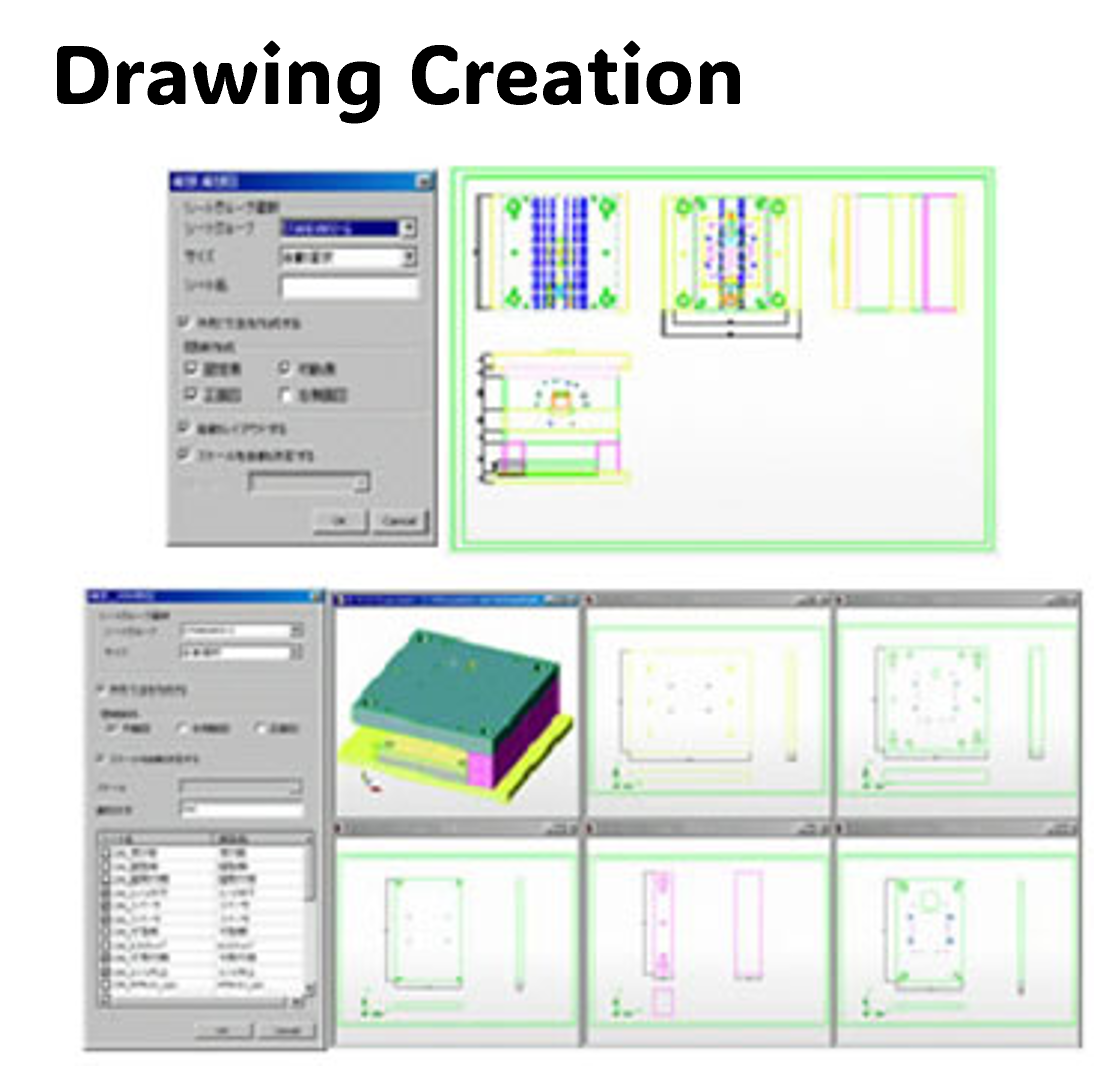
This will significantly help reduce drawing work.
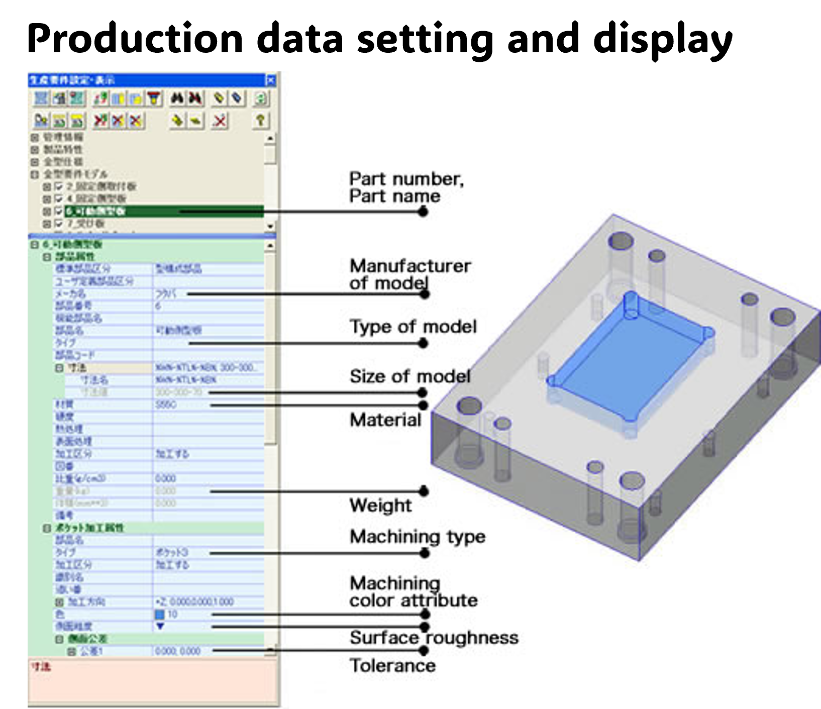
9. Production Information Setup and Display
It takes time to separately compile and pass machining information, such as hole data and processing instructions, to the manufacturing department.
You can set part attributes such as part number and material, as well as machining attributes such as machining method and machining surfaces, and tolerance attributes.
Based on this information, you can automatically generate a parts list, hole list, and pocket list.
In addition, machining data can be transferred to CAM, enabling automatic NC data generation.
This allows design information to be used directly in manufacturing, reducing communication effort and the risk of errors.
CADmeister MOLD CREATOR package brings all mold design processes together in one integrated environment:
From Modeling to Mold Design – Feasibility, Parting, Design, Drawing & Manufacturing Data Management
Please contact us.